Need a Technical Advice?

Hydraulic Scissor Lift: Robust 2-Ton Malaysia

Project Overview

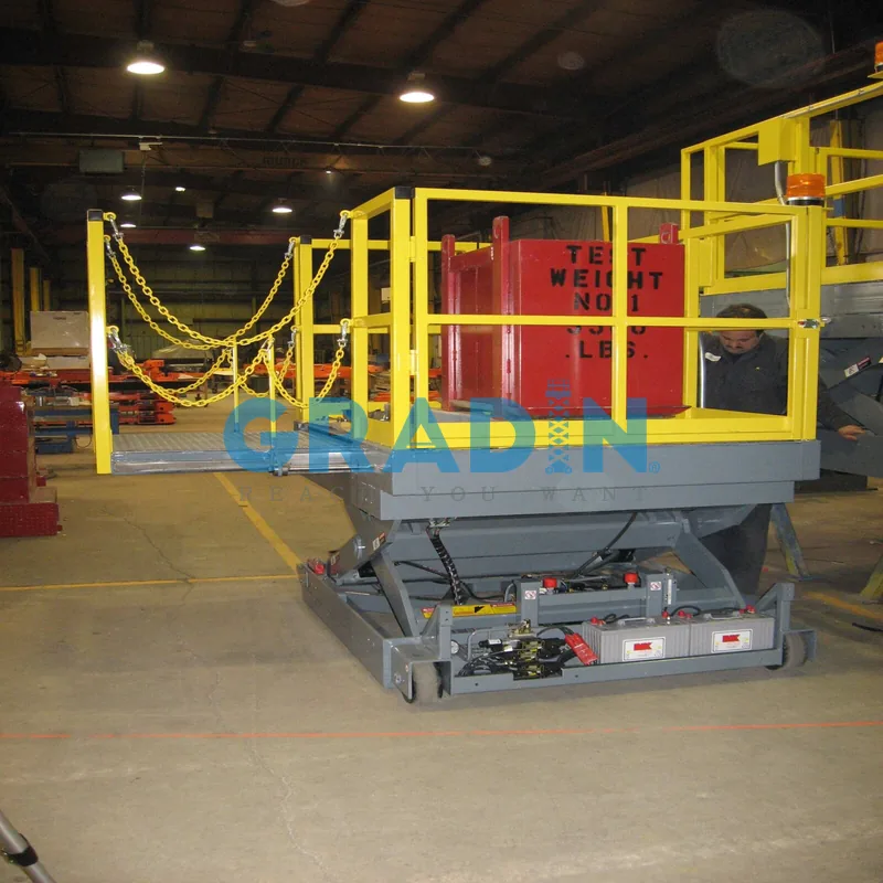
Multi-stage mechanical assembly on oversized plant equipment demands dynamic elevation and rigid platform extension. This case details the custom design, fabrication, and commissioning of an industrial hydraulic scissor lift for an equipment production plant in Selangor, Malaysia.

The project parameters required continuous vertical positioning for assembly personnel and heavy sub-assemblies. The platform supports a 2000 kg safe working load (SWL) with structural validation to a 2500 kg (5512 lbs) proof test load. To span machinery baseplates, the chassis features an 800 mm manual roll-out cantilever deck engineered with positive mechanical stops, maintaining scissor arm alignment under off-center loading.

  • Deployment Region: Selangor, Malaysia. Ambient shop-floor temperatures reach 38°C with relative humidity above 80%. The hydraulic power unit uses ISO VG 68 anti-wear oil and FKM cylinder seals to prevent thermal breakdown and pressure drop during sustained shift cycles.

  • Facility Application: Industrial Machinery Build Station & Large-Structure Torque Assembly.

  • Platform Configuration: Gradin MSL-2000-EXT Heavy-Duty Mobile Scissor Rig. Retracted base elevation: 650 mm; maximum raised tooling height: 2200 mm.

  • Cantilever Load Rating: 2000 kg central deck capacity; 600 kg rated capacity across the 800 mm roll-out extension section.

  • Design Code & Verification: Structural calculation margins, overturning safety factors (1.4+), and manual lateral side-load limits (400 N threshold) meet BS EN 280-1:2022 requirements, verified via third-party load deflection analysis.

  • Floor Protection & Ground Interface: 200 mm diameter, 95 Shore A non-marking polyurethane casters with cast-iron cores protect the anti-static epoxy floor. The base includes dual directional tracking locks and deadman mechanical foot brakes to secure the chassis against drift during torque operations.

Challenge & Solution

Challenge

Integrating a manual roll-out extension deck onto a pantograph mechanism introduces kinematic instability and asymmetric torsional stress. Unlike floor-anchored lift tables, a mobile scissor chassis lacks mechanical ground ties. Any center-of-gravity (CoG) shift toward the cantilever edge reduces static tipping margins. During long tooling setups, structural deflection and valve spool bypass compromise technician safety and component alignment.

  • Cantilever Torque & Structural Distortion: Extending the platform deck outward by 800 mm generates high overturning moment. When operators apply downward vertical load and lateral torque at the cantilever edge, off-center forces twist the dual-scissor leg weldments. In standard scissor frames, this asymmetric load deforms pivot pins, drives slider shoes out of parallel alignment, and causes the arm linkages to bind during descent strokes.

  • Hydraulic Bypass & Uncommanded Drift: Precision mechanical assembly demands fixed work elevations for up to 90 minutes without vertical drop. Standard directional spool valves rely on metal-to-metal clearances. Under high line pressure and 35°C ambient plant heat, fluid slip past the spool lands causes creep exceeding 15 mm per hour. This uncommanded platform descent misaligns bolt patterns and creates severe pinch zones against machine chassis.

  • Lateral Sway Under Dynamic Torque Reactions: Positioning a 2000 kg load at the maximum 2200 mm raised height stresses base rigidity. Linkage designs with single lift cylinders or undersized cross-torque tubes exhibit lateral sway amplitudes above 25 mm when crews operate pneumatic torque tools. This deflection breaches the allowable lateral movement limits set in BS EN 280-1:2022 Clause 5.2.4.

  • Epoxy Surface Degradation & Wheel Point Loads: Gross operating weight exceeds 3200 kg (platform structure plus rated payload). Concentrating this mass across four floor contact points generates extreme ground pressure. Cast nylon wheels chip under point impacts and gouge finished epoxy surfaces. Softer rubber compounds eliminate floor wear but induce chassis bounce, destroying the rigid reference datum needed for tight-tolerance fabrication.

Solution

Transforming the work platform into a rigid assembly jig required resolving two opposing mechanical forces: maximizing horizontal cantilever reach while suppressing lateral pantograph deflection. Engineering the mobile chassis around a stiffened torque-box base, manifold-mounted poppet valving, and dual-rail cantilever guidance eliminated tipping risks and hydraulic creep. Finite element structural models and physical lift prototypes confirmed compliance with international machinery directives.

  • FEA-Optimized High-Stiffness Pantograph Assembly: Primary scissor legs use cold-formed 140 × 80 × 6 mm Q355B structural rectangular hollow sections. Heavy-wall tubular torque tubes (Ø89 × 6 mm) bridge the twin linkages to resist twisting. Under ANSYS finite element stress analysis simulating a 2500 kg (125% proof load) asymmetric point block, peak von Mises stress dropped from 215 MPa to 112 MPa. Transverse platform deflection at the 2200 mm maximum elevation holds at 4.2 mm, keeping structural sway inside allowable EN 280 limits.

  • Precision Dual-Rail Roll-Out Extension Deck Cantilever: An 800 mm manual roll-out cantilever deck provides tool access over wide machinery baseplates. The sub-platform traverses dual Ø40 mm high-carbon induction-hardened chrome guide shafts running on recirculating linear ball bushings. Spring detent plunger pins lock the deck at 100 mm increments, while welded steel stop blocks prevent over-travel. The extension deck supports a 450 kg distributed payload with edge deflection below 3.0 mm, maintaining equilibrium without auxiliary stabilizer outriggers.

  • Zero-Drift Poppet Check Valve & Elevation Hold: To eliminate vertical drift during long bolting cycles, the hydraulic circuit integrates a pilot-operated zero-leakage poppet check valve bolted to the cylinder port manifold. Unlike conventional spool valves, the hardened conical metal-to-metal seat seals line fluid under 18 MPa working pressure. In 90-minute holding trials under 35°C ambient plant temperatures, platform settlement dropped from 16.5 mm per hour to 0.4 mm per hour, providing a stable datum for machine joint assembly.

  • Self-Contained 24V DC Hydraulic Power Unit: Eliminating trailing electrical shop cables, an onboard power pack runs from dual 12V 150Ah deep-cycle industrial AGM batteries. The integrated power unit pairs an internal gear pump delivering 6.2 L/min with a flow-compensated pressure relief valve and an emergency manual lowering valve. A dual-channel deadman push-button pendant provides millimeter-scale micro-jogging for tooling alignment.

  • Anti-Pinch Geometry & Active Safety Integration: Scissor arm linkages maintain a 50 mm clearance gap through the entire motion sweep. Perimeter aluminum safety contact edges wired through dual-channel safety relays halt hydraulic descent within 18 ms of contact, meeting functional safety requirements under ISO 16368:2019 and BS EN 280-1:2022.

  • Heavy-Duty Polyurethane Swivel Casters: The mobile chassis rolls on four Ø200 × 60 mm polyurethane casters equipped with sealed precision ball bearings. Two swivel casters feature dual-action directional tracking locks and foot-actuated wheel tread brakes. The 95 Shore A polyurethane formulation limits maximum floor contact pressure to 1.85 MPa, protecting the factory epoxy finish while holding tractive pull resistance below 180 N for manual positioning.

Technical Specifications

Parameter Category Standard Commercial Baseline Gradin Custom Specification (MSL-2000-EXT) Verification Metric & Compliance Standard
Equipment Model & Type Generic Mobile Scissor Trolley MSL-2000-EXT Heavy-Duty Scissor Rig Serialized fabrication data plate & FAT dossier
Rated Main Platform Capacity 1000 kg (Center distributed load) 2000 kg (Uniformly distributed payload) Static overload proof test at 125% (2500 kg / 5512 lbs)
Cantilever Outreach Stroke Fixed deck edge (0 mm reach) 800 mm manual roll-out cantilever deck 450 kg rated extension payload; ISO 16368 Clause 5.4.1
Working Elevation Range 850 mm to 1600 mm static stroke 650 mm collapsed to 2200 mm raised height Continuous ergonomic tooling height adjustment
Main Platform Footprint 1800 mm L × 900 mm W (Smooth sheet) 2400 mm L × 1200 mm W (Checkered plate) Slip resistance rating R11; anti-wear tread profile
Cantilever Deck Dimensions Non-applicable 800 mm L × 1100 mm W (Non-slip surface) Twin Ø40 mm chrome guide shafts; linear ball bushings
Scissor Arm Cross-Section 100 × 50 × 4 mm structural tube 140 × 80 × 6 mm Q355B RHS + Ø89 × 6 mm tube Minimum yield strength 

ReH≥355 MPa

; ANSYS FEA verified

Deflection Under Asymmetric Load 28.5 mm lateral sway (binding prone) 4.2 mm maximum dynamic lateral deflection Verified within BS EN 280-1:2022 deflection limits
Hydraulic Drive Architecture Single central lift cylinder Dual displacement-synchronized cylinders Honed ST52 hydraulic barrels with hard chrome rods
Hydraulic Elevation Hold Standard spool valve (16.5 mm/hr creep) Manifold-mounted poppet check valve Drift under load 

<0.4 mm/hr

 sustained at 18 MPa

Power Source & HPU Setup AC 415V trailing shop cable 24V DC onboard hydraulic power pack (2.2 kW) Twin 12V 150Ah deep-cycle AGM industrial batteries
Battery Autonomy & Duty Cycle Continuous grid tether required 65 full-load lift cycles per battery charge Built-in 24V 25A multi-stage high-frequency charger
Operator Clearance & Pinch Gap 22 mm shear points (hazard zones)
≥50 mm

 constant clearance throughout travel

EN 349 / ISO 13854 minimum human body gap safety
Descent Perimeter Safety Edge None (unprotected scissor scissor-point) 4-sided aluminum extrusion electric trip bar Contact trip circuit cuts hydraulic drop within 18 ms
Running Gear & Floor Interface Ø150 mm hard cast nylon wheels Ø200 × 60 mm 95 Shore A polyurethane casters Floor contact pressure 1.85 MPa; tractive pull 

<180 N
Machinery Safety Directives Standard CE Machinery Directive (basic) Certified BS EN 280-1:2022 & ISO 16368:2019 Third-party Type Test Certificate & CE marking

Project Gallery