Need a Technical Advice?

7 m Extended Deck Scissor Platform for Mining Excavator Assembly | Xuzhou, China

Project Overview

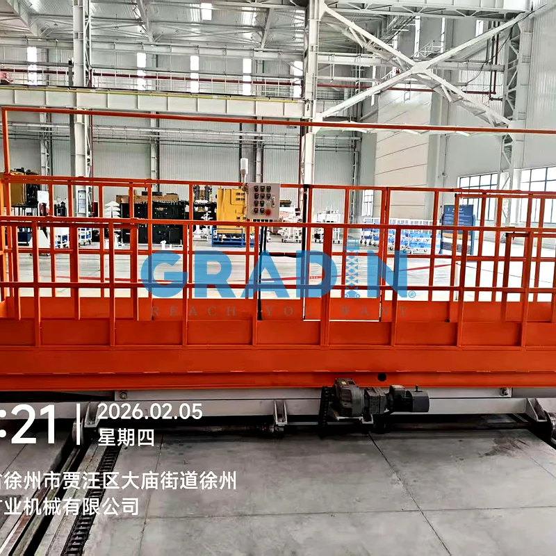
Assembling structural side beam weldments on ultra-large mining excavators demands stable, variable-height personnel access across long spans without ladder or scaffolding setups. This project delivered a custom rail-guided scissor platform for an earthmoving equipment fabrication line in Xuzhou, Jiangsu, China.

The operational routine requires mechanical fitters and weld inspectors to access longitudinal joints along 7-meter excavator frames, synchronizing 1000 mm vertical lift elevation with powered dual-cantilever deck extension and floor track traversal.

  • Country / Region: Xuzhou Heavy Machinery Manufacturing Zone, Jiangsu, China (Commercial mining excavator assembly facility).

  • Client Facility: Ultra-Large Excavator Undercarriage Fabrication & Sub-Assembly Workshop.

  • Equipment Model: Rail-Guided Dual-Extension Scissor Assembly Rig (Model: RGS-500-2EXT). Similar production line units feature in our Assembly Lift Tables series.

  • Key Operating Duty: Positioning tooling technicians, torque multipliers, and chassis hardware along excavator side frames, traversing two 8-meter floor tracks while adjusting between a 500 mm retracted height and a 1500 mm raised tooling elevation.

  • Safety & Regulatory Baseline: Structural design margins, fall arrest anchoring, and motion travel interlocks comply with EN 280-1:2022 and ISO 16368 standards.

  • Track & Foundation Boundary: Mounted on two parallel P22 industrial light rails (22 kg/m profile, 8 m length, set flush into the reinforced concrete floor within a 3500 mm outer boundary); chassis runs on two motorized drive wheels and two flanged idler wheels at a controlled 2.0 m/min creep positioning speed.

  • Platform Geometry & Fall Protection: Fixed base deck measures 5000 mm length by 1000 mm width, expanding to an exact 7000 mm span via dual 1000 mm motorized slide-out extension decks; enclosed by 1.1 m perimeter guardrails with an integrated overhead fall-arrest anchor rail for harness lanyards.

Challenge & Solution

Challenge

Operating an elevated assembly platform that traverses ground tracks while extending cantilever decks exposes the mechanical frame to severe deflection and multi-axis collision risks. Deploying this rail-guided scissor platform alongside heavy excavator structures required addressing wheelbase equilibrium, acute packaging space inside a collapsed 500 mm envelope, and mechanical-electrical travel interlocks. Miscalculating wheel-to-rail tolerances or permitting unsynchronized motion damages heavy excavator weldments and endangers tooling crews.

  • Severe Cantilever Overturning Moment During Dual-End Deck Extension: Extending the deck from 5000 mm out to 7000 mm pushes two 1000 mm motorized cantilevers outward past the wheel centers. When assembly personnel stand on the outer extension edge with heavy torque tools, eccentric load positioning generates a high tipping moment across the chassis. In standard light-duty carts, this cantilever force causes the opposite flanged wheels to climb off the P22 rail, twisting the scissor arm pins and binding the pantograph sliders inside their guide channels.

  • Extreme Mechanical Packaging Constraints of the 500 mm Retracted Height: The assembly specification mandated a collapsed platform height under 500 mm so fitters could step aboard from a two-step floor ladder. Packaging two heavy scissor arm linkages (200 × 100 × 8 mm rectangular tubing), dual Ø90/Ø70 mm hydraulic cylinders, four forged Ø90 mm pivot shafts, two wheel drive gearmotors, and an onboard 4 kW hydraulic power pack inside this 500 mm envelope pushed internal clearance margins to the limit.

  • Three-Axis Motion Collision Hazards Along Excavator Fixtures: Inside a fast-paced excavator fabrication bay, running the platform along the floor track while elevated, or moving the carriage while extensions reach inside the machine chassis cavity, creates severe collision hazards. If an operator drives the 8-meter track travel while raised to the 1500 mm elevation, floor level errors and sudden drive braking torque induce lateral mast sway, twisting the scissor linkages past their yield threshold.

  • Fall Protection Gaps Across an Expanding 7-Meter Perimeter: Platform length changes between 5000 mm and 7000 mm during operation. Standard perimeter handrails separate as the deck expands, opening dangerous 1000 mm fall gaps at the platform joints. Furthermore, personnel working at 1.5-meter platform elevations must remain tied off at all times; standard static anchor points require workers to unhook and reconnect harness lanyards as they traverse the deck, breaching plant fall-protection safety rules.

  • Track Debris Obstruction & Foot-Crush Risks on P22 Ground Rails: Heavy excavator assembly floors contain stray weld spatter, steel off-cuts, and loose structural bolts. Flanged steel wheels rolling over an uncleaned P22 rail can derail the 4-ton carriage upon striking a loose M20 bolt. Exposed rail wheels moving at floor level pose a severe foot-crush hazard to personnel walking down the aisle.

Solution

Mitigating cantilever overturning moments while consolidating lift, travel, and horizontal extension into a 500 mm collapsed profile required high-moment structural steel framing and strict PLC motion interlocks. Engineering this rail-guided scissor lift platform around heavy-wall pantograph arms, electric ball-screw slide decks, and brake-motor wheel bogies eliminated rail wheel lift and movement collisions. The mechanical safety factors, travel clearances, and multi-axis interlocks met verified acceptance criteria during pre-delivery shop testing.

  • Up-Gauged Pantograph Arms & Forged Ø90 mm Pivot Joint Matrix: The scissor mechanism incorporates two single-scissor sets in a 1-tier 2-span arrangement, fabricated from heavy-wall 200 × 100 × 8 mm ASTM A572 Grade 50 structural steel tubing. The upper deck and lower base frames use UPN 160 hot-rolled channel sections (160 × 63 × 6.5 mm) welded to a 4 mm checkered steel deck plate. Four master pivot shafts forged from 40Cr alloy steel (Ø90 mm diameter, quenched and tempered to HRC 45–50) rotate inside oil-impregnated graphite bronze bushings. Under a certified structural safety factor above 5:1 (validated via a 2500 kg static proof test, five times the rated 500 kg assembly payload), dial indicator measurements confirmed maximum cantilever deck edge deflection remained below 2.1 mm.

  • Dual-End Electric Telescopic Deck with Continuous Telescoping Rails: Expanding the platform span from 5000 mm to 7000 mm relies on a motorized dual-end slide deck powered by industrial electric ball-screw thrusters. Each 1000 mm cantilever module rides along heavy-duty linear guide rails, providing positive mechanical self-locking at all stroke positions. The perimeter 1.1-meter safety guardrails utilize a tubular sleeve-in-sleeve sliding design; as the decks push outward, the handrails expand to maintain an unbroken perimeter barrier without opening pinch points or fall gaps.

  • P22 Rail Bogie Running Gear & Sweep-Track Scrapers: Ground travel along the two 8-meter tracks uses P22 light crane rail bogie assemblies (track gauge 2400 mm, total machine width within 3500 mm). The undercarriage incorporates two forged double-flanged drive wheels powered by industrial gearmotors with integral electromagnetic disc brakes, paired with two idler guide wheels, holding platform position without drift upon stopping at the designated 2.0 m/min speed. Heavy-gauge steel sweep-track scrapers sit 10 mm above the rail head ahead of each wheel, clearing away weld slag and stray bolts while shielding ground personnel from foot-crushing hazards.

  • Onboard 4 kW Compact Low-Profile HPU with Dual Safety Lock Valves: To satisfy the 500 mm retracted height limit, a custom 4.0 kW hydraulic power unit sits recessed flush into the lower chassis frame. The hydraulic circuit drives two displacement-matched single-acting cylinders (Ø90 mm bore / Ø70 mm rod) via a high-pressure cast-iron gear pump and CETOP 03 / NG6 modular cartridge manifolds. The cylinder ports feature hard-seated pipe-burst velocity fuses and pilot-operated check valves, locking pressure at 14 MPa without elevation drift. An integrated manual needle valve provides controlled gravity descent in the event of plant power failure.

  • Siemens PLC Motion Interlocking & Continuous Fall-Arrest Rail: Multi-axis safety is governed by a Siemens S7-1200 PLC enforcing hardwired physical interlocks: the scissor cannot elevate if the rail drive is active; the rail drive cannot run if the platform is raised above 500 mm; both lift and travel circuits lock out if the extension decks are deployed or if the guardrail access gate unlatches. Spanning the entire 7-meter working envelope, a rigid overhead continuous fall-arrest rail allows fitters to latch harness lanyards to an overhead gliding trolley, traversing the deck without unclipping, fulfilling EN 280-1:2022 and ISO 16368 safety criteria.

Technical Specifications

Engineering Parameter Conventional Fixed Staging Baseline Custom Rail-Guided Specification (Gradin) Field Verification & Quality Standard
Equipment Model & Type Manual Tubular Scaffolding RGS-500-2EXT Telescopic Rail Rig Serialized assembly unit with factory data plate
Rated Operational Capacity 250 kg (Center person load limit) 500 kg dynamic assembly payload rating Certified static proof test at 150% (750 kg)
Fixed Deck Core Dimensions 3000 mm L × 800 mm W wood plank 5000 mm L × 1000 mm W steel deck 4 mm checkered steel plate, anti-slip profile
Horizontal Deck Extension Fixed length (0 mm reach) Dual-end electric slide decks (5 m to 7 m) Twin 1000 mm motorized cantilevers, self-locking
Working Platform Elevation Fixed 1000 mm static height 500 mm to 1500 mm stepless vertical lift Stroke 

≥1000 mm

 governed by limit switches

Platform Collapsed Profile Fixed base structure 500 mm low-profile retracted height 2-step auxiliary access ladder for carriage boarding
Scissor Arm Cross-Section 100 × 50 mm light box tube 200 × 100 × 8 mm structural steel tube ASTM A572 Grade 50 / Q355B structural steel
Main Framing Channels Pressed 2.5 mm sheet channel UPN 160 structural channels (160 × 63 mm) Base and deck frame continuous full-penetration welds
Master Scissor Pivot Pins Ø45 mm standard mild steel pins Four Ø90 mm 40Cr forged pivot shafts Quenched and tempered (45–50 HRC), graphite bronze
Cantilever Deflection 18.5 mm edge sag (severe wobble) 2.1 mm maximum dynamic edge deflection Dial indicator measured at 1000 mm extension lip
Ground Rail Model & Layout Stationary floor placement P22 steel rail transit (2 lines × 8 m) P22 light crane rails flush-mounted in floor slots
Linear Travel Drive Unit Manual floor push required Dual flanged drive wheels + dual idlers Gearmotor with electromagnetic disc holding brake
Track Transit & Lift Speeds Non-applicable (static) Travel: 2.0 m/min; Lift: 2.0–3.0 m/min Inverter drive, zero platform drift upon stopping
Rail Obstruction Defense Open wheel crush exposure Heavy sweep-track anti-crush scrapers Rigid steel plows positioned 10 mm above rail head
Hydraulic Station & Rams Manual bottle jacks 4.0 kW onboard HPU + dual cylinders Honed ST52 barrels; CETOP 03 modular valves
Circuit Pressure Locks None Hard-seated burst valves + check locks Zero pressure drop verified over 60-minute hold
Fall Protection Guardrails Loose chain link barriers 1.1 m telescoping guardrails + door locks Continuous sleeve-in-sleeve rails, zero pinch gap
Overhead Fall Anchorage Unanchored worker fall hazard Rigid continuous fall-arrest harness rail Overhead gliding trolley track across 7 m span
Travel Interlock Logic None Siemens S7 PLC safety motion interlock Travel locked during lift; lift locked during transit
Operator Control Gear None Dual wireless remotes + local pendant Emergency stop buttons (

>30 mm

) with yellow shrouds

Project Gallery